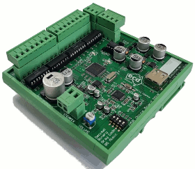
USB VOICE BOARD SPV4
USB Voice Board

USB VOICE BOARD SPV4
Price: RFQ
The USB Voice Board SPV4 (Serial Protocol) outputs floor, direction and message MP3 files which are played in the elevator car via the supplied speaker.
The Voice Board has the option of receiving input information directly with 24VDC inputs or via Serial Data (controlled by ECD Encoder Board).
The Voice Board requires a USB memory stick, loaded with MP3 files, to be inserted for programming. Once programmed, the USB stick is removed as all MP3 files are now stored on the Voice Board data-flash.
Note: Format USB memory stick prior to program any floor messages (MP3 files).
Features
- Direct 24VDC inputs or Serial Data input.
- 8 inputs (1-8) for floor messages. Direct inputs may be configured as Decimal, Binary or Gray Code.
- Inputs may be positive or negative switched.
- Trigger (TRIG) input for initiating floor messages.
- 2 direction inputs (DN, UP) for direction messages.
- 4 special message inputs.
- Background music on/off selectable. BG music turns off 30s after last floor announcement.
- Adjustable volume.
- Program Voice Board with USB stick. USB stick removed once programmed.
- Programming software available.
LED Indicators
- Yellow LED (Programming): Hard on to indicates MP3 files are being copied from USB memory stick to the Voice Board dataflash.
- Red LED (Run): Flashing to indicates that the microprocessor is running
Wiring using serial data input
- Ensure the Serial Input link jumper is installed.
- A 24VDC supply (100-150mA) is wired to the +24V and 0V terminals. A twisted pair looped through a ferrite core is recommended. Nb: The direct inputs are wired to the Encoder Board.
- Select Background music on/off with BG Music DIP switch.
Wiring using direct inputs
- Ensure the Serial Input link jumper is NOT installed for Direct input operation.
- A 24VDC supply (100-150mA) is wired to the +24V and 0V terminals. A twisted pair looped through a ferrite core is recommended.
- All inputs use the “C” common terminal as their reference. If “C” is wired to 0V then the inputs shall be +24V. If “C” is wired to +24V then the inputs shall be 0V.
- Inputs 1 to 8 and TRIG – When any of the floor Inputs (1-8) is turned on and TRIG is switched from off to on, the floor message shall be played. Floor inputs may be either Decimal, Binary or Gray Code, selectable via DIP switches.
- UP, DN input – Direction of travel messages, “going up or “going down”, shall be sounded after a floor input message, while a direction input is on.
- Inputs 9,10,11,12 – Special message inputs. Input 13. N/A.
- Select Background music on/off with BG Music DIP switch.
